ch5.network_in_motion
Ch 5. Network in motion
Understanding Networking in HFT Systems
-
Purpose:
- Trading systems need to receive market data and send orders to exchanges.
- Processes within these systems communicate to share information, such as the position of an instrument.
-
Networking Basics:
- Defines how devices are interconnected.
- Essential for data transfer between machines and exchanges.
- Underpins all HFT systems, requiring careful design consideration.
-
Key Components:
- Network Interface Card (NIC):
- Ensures communication in the system.
- Connects the computer where software runs to the outside world.
- Network Interface Card (NIC):
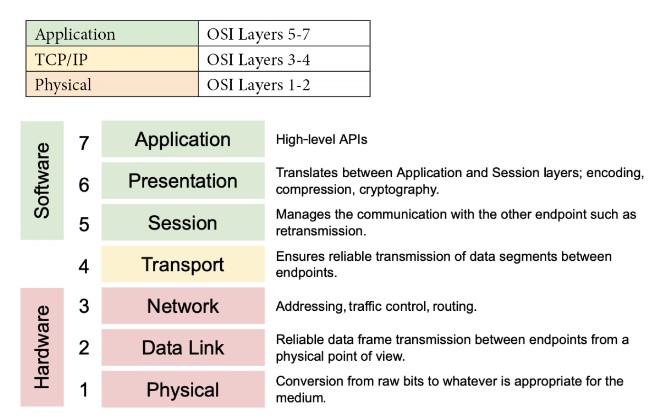
Network Conceptual Models: OSI Model
Overview
- OSI Model: Conceptual framework depicting how computers communicate in networked environments.
- Seven Independent Layers: Each layer has specific functions and communicates only with its adjacent layers.
Layers of the OSI Model
-
Physical Layer:
- Function: Handles the physical connection between devices and the transmission of raw binary data over a communication medium.
- Responsibilities: Defines electrical, optical, and mechanical characteristics of network devices and media. Deals with physical aspects like cables, switches, and the transmission of bits.
- Media: Optical fiber, copper cable, satellite.
- Examples: Network hubs, cabling, repeaters, network adapters, modems, Network cables (Ethernet, fiber optics), network interface cards.
- Characteristics: Latency, bandwidth, attenuations.
-
Data Link Layer:
- Function: Provides node-to-node data transfer and handles error detection and correction that may occur at the physical layer during the transmission of data.
- Responsibilities: Encapsulates packets into frames, performs error detection/correction, and manages access to the physical medium. It ensures reliable communication over the physical network medium by managing how data is formatted, transmitted, and detected on the local network.
- Techniques: Parity checks, cyclic redundancy checks (CRCs).The Data Link Layer encapsulates network layer packets into frames. It defines the start and end of each frame for proper interpretation by the receiving system.
- Examples: Ethernet, Wi-Fi, and MAC (Media Access Control) / hardware addresses.
-
Network Layer:
- Function: Logical addressing and routing of data frames to their destinations across multiple networks..
- Responsibilities: Determines the best path for data packets to travel across networks and handles packet forwarding and routing.
- Protocol: Internet Protocol (IP), mainly IPv4 in financial sectors due to its simplicity.
-
Transport Layer:
- Function: Ensures reliable data transfer between two devices, including error recovery and flow control.
- Protocols: Transmission Control Protocol (TCP) and User Datagram Protocol (UDP).
- Responsibilities: Manages end-to-end communication, error recovery, and flow control. Ensures data is delivered accurately and in order. Sequencing, packet size management, data transfer.
- Examples: TCP (Transmission Control Protocol), UDP (User Datagram Protocol).
-
Session Layer:
- Function: Manages sessions or connections between applications, providing session establishment, maintenance, and termination.
- Responsibilities: Controls dialogues (connections) between applications. Manages session establishment, maintenance, and termination.
- Examples: NetBIOS, RPC (Remote Procedure Call).
-
Presentation Layer:
- Function: Translates, encrypts, and compresses data for the application layer. Ensures data is in a readable format for the application layer.
- Responsibilities: Handles data translation, encryption/decryption, and data compression.
- Examples: SSL/TLS (for encryption), JPEG, GIF (image formats).
-
Application Layer:
- Function: Provides network services directly to end-user applications. It’s the layer closest to the end-user.
- Responsibilities: Interfaces with end-user applications and provides services like file transfers, email, and network management.
- Examples: HTTP (HyperText Transfer Protocol), FTP (File Transfer Protocol), SMTP (Simple Mail Transfer Protocol).
Simplified Model
- Software Layer (Layers 5-7): Deals with application-level processes.
- Transport Layer (Layer 4): Acts as a bridge between software and hardware layers.
- Hardware Layer (Layers 1-3): Deals with physical transmission of data.
Network Communications in HFT Systems
Key Considerations
- Microsecond Sensitivity:
- Microseconds matter in HFT, necessitating careful consideration of network components.
- Innovations in networking can significantly impact trading performance.
Abstract Model of a Network
- Communication Process:
- Devices communicate through a physical connection to a network device like a switch.
- The switch moves the packet across the network to the recipient.
Components
-
Network Interface Card (NIC):
- Number of Ports: NICs can have one, two, four, or six ports, allowing multiple network access or multiple NICs on the same machine.
- Port Types:
- RJ-45: Uses twisted-pair cables (Cat5, Cat6).
- BNC: Connects via coaxial cables.
- Optical Port: Works with fiber-optic cables.
- Network Speed:
- Standard speeds: Single-lane 100 Gbps, 25 Gbps, 10 Gbps.
- Multi-lane speeds: 400 Gbps, 50 Gbps, 40 Gbps.
- Common in data centers and financial applications: 10 Gbps and 25 Gbps Ethernet.
- Application-Specific Integrated Circuit (ASIC):
- Interfaces with the host PC over PCIe and the network.
-
Network Devices:
- Hub:
- Connects a LAN network, replicating packets to all recipients.
- Mostly obsolete but revived for HFT by Metamako/Exablaze for latency-saving.
- Switch:
- Operates at the data link layer (layer 2) and sometimes the network layer (layer 3).
- Filters and forwards packets across the LAN.
- Router:
- Joins at least two networks and facilitates packet delivery between them.
- In HFT systems, routers are located at gateways to forward packets efficiently.
- Hub:
Impact on Latency
- Primary Components Introducing Latency:
- Routers: Facilitate packet delivery across networks.
- Switches: Filter and forward packets within the LAN.
- NICs: Interface computers with the network.
Network Communications in HFT Systems
- Key Considerations: Microsecond Sensitivity:
- Designers prioritize communication modes due to the critical importance of microseconds.
- Innovations like microwave networks and Cisco switches can significantly impact trading performance.
Abstract Model of a Network
- Communication Process:
- Devices communicate via physical connections to network devices like switches.
- Switches move packets across the network to recipients.
Components
-
Network Interface Card (NIC):
- Number of Ports:
- NICs can have 1, 2, 4, or 6 ports, allowing multiple network access. Multiple NICs can be installed on the same machine.
- Port Types:
- RJ-45: Uses twisted-pair cables (Cat5, Cat6).
- BNC: Connects via coaxial cables.
- Optical Port: Works with fiber-optic cables.
- Network Speed:
- Single-lane speeds: 100 Gbps, 25 Gbps, 10 Gbps.
- Multi-lane speeds: 400 Gbps, 50 Gbps, 40 Gbps.
- Common speeds: 10 Gbps and 25 Gbps Ethernet in data centers and financial applications.
- Application-Specific Integrated Circuit (ASIC):
- Interfaces with the host PC over PCIe and the network.
- Number of Ports:
-
Network Devices:
- Hub:
- Connects a LAN network, replicating packets to all recipients.
- Mostly obsolete but revived for HFT by Metamako/Exablaze for latency-saving.
- Switch:
- Operates at the data link layer (Layer 2) and sometimes the network layer (Layer 3).
- Filters and forwards packets across the LAN.
- Router:
- Joins at least two networks and facilitates packet delivery between them.
- In HFT systems, routers are located at gateways to forward packets efficiently.
- Hub:
Impact on Latency
- Primary Components Introducing Latency:
- Routers: Facilitate packet delivery across networks.
- NICs: Interface computers with the network.
- Switches: Filter and forward packets within the LAN.
Comprehending how switches work
Key Concepts
- Ingress and Egress:
- Ingress: Input of data into the switch.
- Egress: Output of data from the switch.
flowchart LR
    IngressInterface[Ingress Interface] --> |MAC address|MatchAction[Match Action]
    MatchAction --> GlobalBuffer[Global buffer]
    GlobalBuffer --> EgressPortBuffer1[Egress port buffer]
    GlobalBuffer --> EgressPortBuffer2[Egress port buffer]
    GlobalBuffer --> EgressPortBuffer3[Egress port buffer]
    GlobalBuffer --> EgressPortBuffer4[Egress port buffer]
    EgressPortBuffer1 --> EgressInterface[Egress Interface]
    EgressPortBuffer2 --> EgressInterface
    EgressPortBuffer3 --> EgressInterface
EgressPortBuffer4 --> EgressInterface- Components:
- Ingress Interface: Receives incoming packets.
- Match Action: Determines forwarding rules based on packet headers.
- Global Buffer: Temporarily stores packets before they are routed to the appropriate egress port buffer.
- Egress Port Buffers: Store packets before they are sent out via the egress interface.
- Egress Interface: Sends out packets to their destinations.
Switch Operations
-
Configuring Packet Forwarding:
- Basic Operation: Observes MAC addresses and switches traffic to corresponding ports.
- Advanced Switches: Support Layer 3/4 actions based on IP addresses or ports.
-
Forward/Filter Decisions:
- Configuration Tables: Used to forward or discard packets as needed.
- Dynamic Table Generation: Tables are created and updated on the fly based on routing updates.
Packet Handling Process
-
Parser:
- First to process new packets.
- Identifies and extracts header information from packets.
- Packet body is buffered independently.
-
Match-Action Tables:
- Ingress Match-Action:
- Decides the egress port(s) and routing queue.
- May modify packet headers.
- Actions: Forward, duplicate, discard, or control flow triggering.
- Egress Match-Action:
- Modifies packet headers for specific instances (e.g., multicast).
- Tracks state through action tables (counters, policers).
- Ingress Match-Action:
-
Metadata:
- Carried between stages like packet header fields.
- Includes ingress port, transmit destination and queue, and table-to-table data.
Bandwidth, throughput, and packet rate/size
Definitions
-
Bandwidth:
- Theoretical maximum number of packets exchanged between two hosts.
- Indicates potential capacity of the network.
-
Throughput:
- Actual rate at which packets reach their intended destination.
- Measures real packet delivery, not just theoretical capacity.
- Reflects average data delivery performance.
Importance
- Packet Delivery:
- High-performance service requires effective packet delivery.
- Losing packets can lead to issues like incoherent order books in financial applications.
Performance Metrics
-
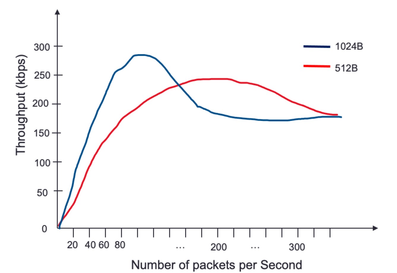
Packet Size:
- Larger packets can increase the amount of data sent, thus boosting throughput.
- Throughput initially rises with packet size but eventually reaches a saturation point.
-
Packet Rate:
- Number of packets sent per second.
- Increasing packet rate generally increases throughput up to a certain point.
Network Throughput Behavior
-
Throughput vs. Packet Rate:
- Throughput improves as packet rate increases due to more data being transmitted.
- Beyond a certain point, throughput declines as the network approaches saturation.
-
Impact of Packet Size:
- Larger packets increase throughput more quickly than smaller packets.
- Example: Throughput peaks faster with 1,024-byte packets compared to 512-byte packets.
Challenges
- Buffering:
- Occurs when multiple ingress interfaces try to send outbound packets to the same egress interface.
- Can happen when maximum throughput of an interface is reached, leading to delays.
Switch Queuing
Key Concepts
- Function of a Switch:
- Routes packets to proper recipients.
- Uses buffers to store incoming data waiting to be processed.
- Essential to prevent data loss and manage incoming data exceeding processing speed.
Queuing Mechanism
flowchart LR
InputPort[Input Port] --> Buffer[Buffer] --> OutputPortQueue[Output Port Queue] --> OutputPort[Output Port]-
Components:
- Input Port: Receives incoming packets.
- Buffer: Temporarily stores packets waiting to be processed.
- Output Port Queue: Holds packets ready to be sent to the output port.
- Output Port: Sends packets to their destination.
-
Process:
- Packet received on the input port.
- Switch looks up the destination and identifies the output port.
- Packet is placed in the output port queue.
-
Challenges:
- Saturation:
- Large data streams can saturate the output port queue.
- Saturation causes significant latency and potential packet loss (packet drops) if the buffer is full.
- Packet drops disrupt trading by preventing the construction of accurate order books.
- Saturation:
-
Head-of-Line (HOL) Blocking:
- Definition:
- Occurs when packets are held up by a packet at the front of the queue.
- In network switches or routers, packets are often queued for processing or transmission. If the packet at the front of the queue (the "head of line") is delayed or blocked due to various reasons (e.g., congestion, errors, or resource limitations), all subsequent packets in the queue must wait, even if they could otherwise be processed or transmitted without delay.
- Occurs when packets are held up by a packet at the front of the queue.
- Consequences:
- Increases latency and can cause packet reordering.
- Switch processes other packets directed to different outputs, resulting in out-of-order packet delivery.
- Definition:
Impact on Packet Delivery
-
Buffering:
- Prevents data loss by storing packets when incoming data exceeds processing speed.
- Essential for maintaining data integrity and order.
-
Latency and Packet Loss:
- Full buffers and saturated queues increase latency.
- Packet drops disrupt critical trading functions like order book maintenance.
Switching Modes
Overview
- Switching Mechanism:
- The method by which a switch processes and forwards packets.
- Decision to forward is based on the destination MAC address.
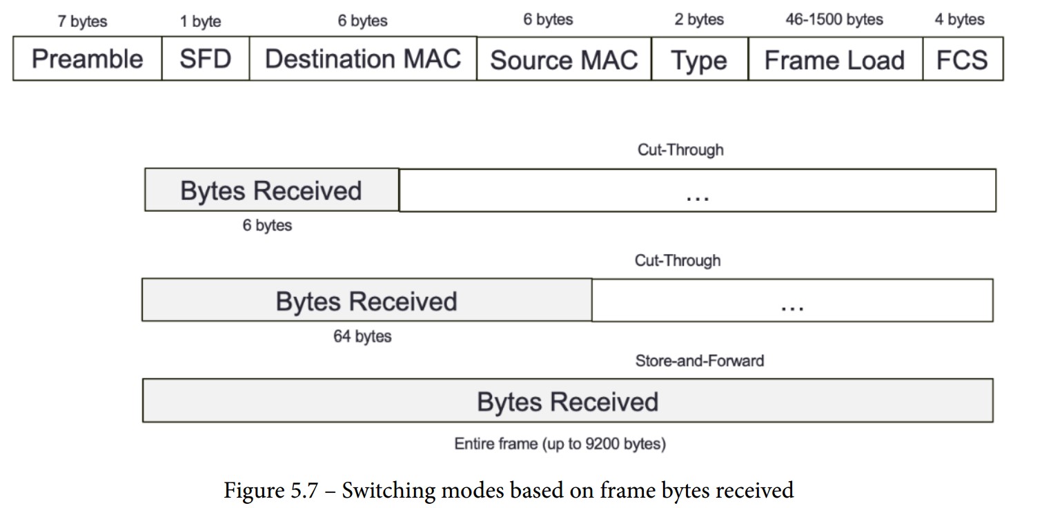
Store-and-Forward Switching Mode
-
Process:
- The switch receives the entire frame before forwarding.
- Uses a destination MAC address lookup to decide forwarding.
- Validates frame integrity using the frame-check-sequence (FCS) field.
- Discards frames with mismatched CRC values.
- Checks if destination and source MAC addresses match.
- Environments requiring high data integrity may prefer store-and-forward switching.
-
Frame Sizes:
- Accepts frame sizes between 64 bytes and 1,518 bytes.
- Frames outside this range are discarded.
-
Delay:
- Higher delay compared to cut-through modes due to complete frame reception.
Cut-Through Switching Mode
-
Process:
- Makes forwarding decisions based on the first few bytes of the frame.
- Faster than store-and-forward as it doesn't wait for the entire frame.
- High-speed, low-latency environments like HFT may prefer cut-through switching.
-
Types:
- Fragment-Free Switching:
- Parses the first 64 bytes of a frame before forwarding.
- Balances speed and error checking.
- Fast-Forward Switching:
- Forwards the frame upon receiving the destination MAC address (first 6 bytes).
- Fastest mode with minimal delay, but less error checking.
- Fragment-Free Switching:
Comparison
-
Store-and-Forward:
- Advantages:
- Ensures data integrity and accuracy.
- Discards invalid frames to prevent errors.
- Disadvantages:
- Higher delay due to complete frame reception.
- Advantages:
-
Cut-Through:
- Advantages:
- Lower latency as forwarding decisions are made quickly.
- Suitable for environments where speed is critical.
- Disadvantages:
- Less error checking compared to store-and-forward.
- Potential for forwarding corrupted frames in fast-forward mode.
- Advantages:
Layers Where Switches Perform Packet Forwarding
Layer 1 Switching (Physical Layer)
- Definition: Part of the OSI model's physical layer.
- Function: Establishes physical connections between ports.
- Acts as an electronic and programmable patch panel.
- Configurable via software instructions for test topologies.
- Characteristics:
- Does not read, alter, or use packet/frame headers.
- Invisible to data with very low latency.
- Ideal for testing environments, providing transparent connections akin to a direct patch cable.
- Example: Arista/Cisco Layer 1 switches.
Layer 2 Switching (Data Link Layer)
- Definition: Also known as multiport bridge.
- Functions:
- Physical Layer Data Transfer: Transports data across physical connections.
- Error Checking: Verifies any frames received and sent for errors.
- Mechanism:
- Utilizes MAC addresses to forward frames to correct recipients.
- Maintains a forwarding table with all received MAC addresses for efficient data forwarding.
- Cannot transfer packets based on IP addresses and lacks prioritization mechanisms.
- Usage: Efficiently forwards data within local networks using MAC addresses.
Layer 3 Switching (Network Layer)
- Definition: Functions as a router with advanced IP routing capabilities.
- Functions:
- Smart IP Routing: Analyzes and routes packets based on source and destination IP addresses.
- Subnet Linking: Connects devices within the same subnet.
- Mechanism:
- Combines the functionalities of both switches and routers.
- Capable of handling IP address-based packet transfers and providing efficient routing within and between subnets.
Network Address Translation (NAT)
Definition
- NAT: Converts private IP addresses into public IP addresses, enabling multiple devices to share a single public IP address.
Process
- Request Routing:
- A machine sends a packet with a request to the exchange through a router.
- The router converts the private source IP address to a public one.
- The exchange responds to the router's public IP address.
- The router forwards the response to the correct private IP address on the local network.
Impact on Performance
- Resource Intensity:
- NAT requires reading and modifying the header and payload of every IP packet.
- This process increases CPU and memory usage.
- Potential for reduced throughput and increased packet delay.
- Performance in HFT:
- Critical to understand NAT's performance impact on routers in high-frequency trading environments.
- Modern switches can perform static NAT in an ASIC with minimal performance penalties.
- Increasingly, switches can also perform dynamic NAT efficiently.
Important Protocol Concepts
Definition of Protocols
- Protocol:
- A set of rules that governs the communication between devices in a network.
- Functions like a language that components agree upon for effective communication.
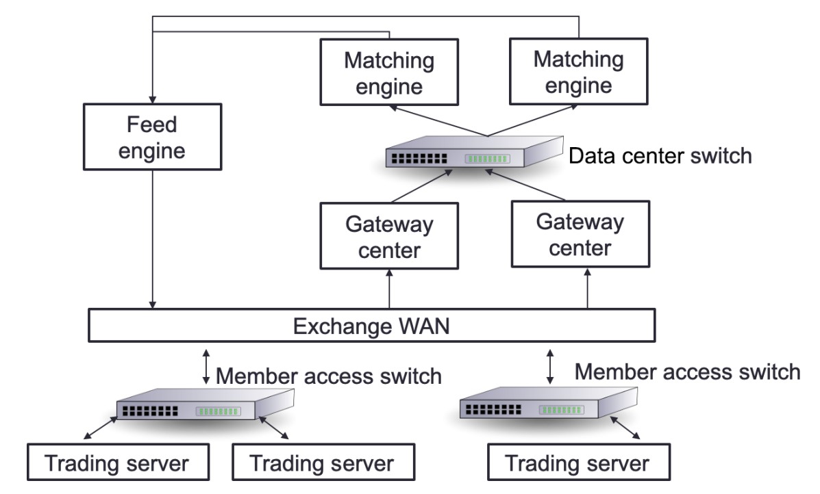
Network Infrastructure in Trading Systems
- Key Components:
- Trading Exchange: Where orders are matched.
- Market Data-Feed Handlers: Deliver data from the stock exchange to market participants.
- Market Participants: Entities placing orders in the trading system.
Communication Flow
- Orders and Matching:
- Orders from market participants are sent to the trading exchange through gateway servers.
- Data-Feed Handlers:
- Collect market data from the stock exchange.
- Deliver data to market participants with minimal delay.
Protocols Used
- FIX Adapted for STreaming (FAST) Protocol:
- Used for transporting market data efficiently.
- Designed to minimize latency and handle high-frequency data transmission.
Using Ethernet for HFT Communication
Overview of Ethernet
-
Ethernet Protocol:
- Commonly used to link devices in wired LANs or WANs.
- Specifies data structure and transmission rules for device communication.
- Reliable, fast, and secure.
-
Development and Standards:
- Designed by IEEE 802.3 working group in 1983.
- Standards include 802.3X and 802.11X.
- Examples: 100BASE-T (Fast Ethernet), still in use today.
IPv4 in Network Communication
-
Network Layer Protocol:
- IP operates at the OSI model's network layer.
- TCP and UDP operate at the internet layer.
- IP identifies hosts by logical addresses and routes data between them.
-
IP Addressing System:
- Uses 32-bit logical addresses.
- Provides best-effort delivery, without guaranteed packet delivery.
IPv4 Addressing Modes
-
Unicast Mode:
- Data sent to a single designated host.
- Destination Address field contains the 32-bit IP address of the target host.
- Typical use: Client transmits data to a specific server.
-
Broadcast Mode:
- Data sent to all hosts in a network segment.
- Destination Address field contains the broadcast address: 255.255.255.255.
- All hosts on the network process the packet.
- Rarely used in HFT due to lack of control and potential overhead.
-
Multicast Mode:
- Data sent to multiple designated hosts.
- Destination Address field contains an address starting with 224.x.x.x.
- Hosts subscribe to specific multicast feeds using IGMP.
- Switches with IGMP snooping replicate multicast traffic only to subscribed hosts.
- Switches without IGMP snooping treat multicast as broadcast traffic.
UDP and TCP for the Transport Layer
Overview
- Common Usage:
- TCP/IP or UDP over Ethernet is the standard communication protocol used by stock exchanges and market participants.
- UDP: Often used for non-essential data like market data feeds to minimize latency and overhead.
- TCP: Used for critical data such as orders to ensure reliable delivery.
TCP (Transmission Control Protocol)
-
Functionality:
- Provides reliable, connection-oriented communication.
- Establishes a connection through a handshake before data transmission.
- Ensures error checking and error recovery.
- Delivers data as an end-to-end (E2E) byte stream.
-
Characteristics:
- Connection-Oriented: Requires a connection to be established.
- Reliable: Guarantees delivery, order, and integrity of data.
- Handshake: Necessary to start communication.
-
Critical Concepts of a TCP "Connection"
- A TCP connection is a stateful, reliable, and ordered communication channel that requires a formal establishment process and provides robust mechanisms for error handling and data integrity.
-
Establishment:
- Three-Way Handshake: The process involves SYN, SYN-ACK, and ACK packets to establish the connection between two endpoints.
-
Bidirectional Communication:
- Full Duplex: Allows simultaneous two-way data transmission.
-
State Management:
- Connection States: Tracks the progress and status (e.g., SYN_SENT, ESTABLISHED).
- Session Information: Includes sequence and acknowledgment numbers for reliable data delivery.
-
Reliability and Ordering:
- Error Checking: Ensures data integrity through error detection and retransmission.
- Data Ordering: Guarantees data is received in the same order it was sent.
-
Termination:
- Four-Way Handshake: Ends the connection with FIN and ACK packets to close it gracefully.
UDP (User Datagram Protocol)
-
Functionality:
- Provides fast, connectionless communication.
- Suitable for broadcast and multicast transmissions.
- Does not ensure packet delivery or error recovery.
-
Characteristics:
- Connectionless: No need to establish a connection.
- Fast: Lower latency due to lack of error-checking mechanisms.
- Unreliable: No guarantee of packet delivery, order, or integrity.
Main Differences
-
Connection:
- TCP: Connection-oriented.
- UDP: Connectionless.
-
Speed and Error Handling:
- UDP: Faster, no error checking, and no recovery.
- TCP: Slower due to error checking and recovery mechanisms.
-
Communication Initiation:
- TCP: Requires a handshake.
- UDP: Does not require a handshake.
-
Error Checking:
- TCP: Checks for errors and recovers from them.
- UDP: Checks for errors and discards problematic packets.
Usage in HFT
-
UDP:
- Preferred for market data due to lower latency.
- Datagram-Oriented Delivery: Provides lower latency but makes recovery from data loss more complex.
- Multicast Support: Suitable for many-to-many communication, which is incompatible with connection-oriented protocols.
- Trend: Increasing use of UDP for Orders (UFO) to send orders faster.
-
TCP:
- Used for critical order data where reliable delivery is essential.
Mitigating UDP Limitations
- Application-Layer Solutions:
- Use of sequence numbers to track packet order.
- Out-of-band mechanisms to request retransmission of missing packets.
Designing Financial Protocols for HFT Exchanges
Communication Between Trading Systems and Exchanges
-
Protocol:
- A set of rules that governs communication between trading systems and exchanges (venues).
- Each venue may use a different protocol, requiring trading systems to understand multiple protocols.
-
Connection Process:
- Logon: Establishes who the trade initiator and recipient are, and how the connection will be maintained.
- Enquiry: Specifies expectations from the venue, such as trading or receiving price updates by subscription.
- Order Reception: Receives orders and pricing updates.
- Heartbeats: Sends periodic messages to maintain the connection.
- Logoff: Terminates the connection.
FIX Protocol
-
Overview:
- The Financial Information eXchange (FIX) protocol is the most widely used protocol in trading.
- Established in 1992 for real-time securities exchange.
- Covers various asset classes including foreign exchange (FX), fixed income (FI), derivatives, and clearing.
- String-based and platform-agnostic, making it readable and flexible.
-
Message Types:
- Administrative Notifications: Do not include financial information.
- Program Messages: Used to get pricing changes and orders.
-
Message Structure:
- Consists of key-value pairs (similar to a dictionary or map).
- Keys are predefined tags (numbers representing specific characteristics).
- Values can be numerical or textual.
- Pairs are separated by the character "|".
- Example: "44=1.23|38=100000" where 44 is the price tag and 38 is the quantity tag.
-
Message Prefix and Suffix:
- Prefix: "8=FIX.X.Y" denotes the FIX version.
- Suffix: "10=nn" is the checksum, ensuring message integrity by summing the binary values of the message content.
Example FIX Message
8=FIX.4.42|9=76|35=A|34=1|49=TRADER1|52=20220117-12:11:44.224|56=VENUE1|98=0|108=30|141=Y|10=134- Key Fields:
- 8: BeginString (e.g., "FIX.4.42" for version 4.42).
- 9: BodyLength (number of characters from tag 35 to tag 10).
- 35: MsgType (specifies the type of message).
- 49: SenderCompID (identifies the sender).
- 52: SendingTime (timestamp).
- 56: TargetCompID (identifies the recipient).
- 10: Checksum (ensures message integrity).
Protocols for FIX Communication
To facilitate trading, a trading system requires two connections: one for receiving price updates and another for placing orders. The FIX protocol accommodates this by utilizing distinct messages for each type of connection.
Price Changes
When constructing a trading system, the primary feed to secure is price updates. These updates represent orders from other market participants. The trading system initiates a connection with the exchange to establish and subscribe to these updates. In this scenario, the trading system acts as the initiator, and the exchange serves as the acceptor.
Process Overview
- Logon: The trading system starts a session to receive price updates.
- Subscription: The trading system subscribes to updates for one or more instruments.
- Price Update Streaming:
- Full Snapshot: Initial comprehensive data on instrument prices.
- Increment Refresh: Subsequent updates reflecting changes.
- Termination: The trading system ends the session.
Sequence Diagram
sequenceDiagram
    participant Exchange as Exchange<br>(acceptor)
    participant TradingSystem as Trading System<br>(initiator for price update)

    TradingSystem ->> Exchange: 1. Logon (Start a session to get price updates)
    Exchange ->> TradingSystem: 1.a Logon acknowledgement
    TradingSystem ->> Exchange: 2. Subscription to one or many instruments
    Exchange ->> TradingSystem: 2.a Price update streaming (Full Snapshot)
    Exchange ->> TradingSystem: 2.b Price update streaming (Full Snapshot)
    Note over TradingSystem, Exchange: OR
    Exchange ->> TradingSystem: 2.b Price update streaming (Increment Refresh)
    Note over TradingSystem, Exchange: ...
    TradingSystem ->> Exchange: Bye
    Exchange ->> TradingSystem: Bye
Orders
The second essential connection for a trading system is the order feed. This connection facilitates communication with the exchange for placing and managing orders. The trading system (initiator) establishes this communication channel with the exchange (acceptor).
Process Overview
- Logon: The trading system starts a session to manage orders.
- New Order: The trading system sends new orders to the exchange.
- Order Updates:
- Order Acknowledgement or Rejection: Confirmation of order reception.
- Order Filled: Notification when an order is executed.
- Amend/Cancel Orders: The trading system can amend or cancel existing orders.
- Termination: The trading system ends the session.
Sequence Diagram
sequenceDiagram
    participant Exchange as Exchange<br>(acceptor)
    participant TradingSystem as Trading System<br>(initiator for orders)

    TradingSystem ->> Exchange: 1. Logon (Start a session to get price updates)
    Exchange ->> TradingSystem: 1.a Logon acknowledgement
    TradingSystem ->> Exchange: 2. New Order
    Exchange ->> TradingSystem: 2.a Order Ack or Order Rejected
    Exchange ->> TradingSystem: 2.b Order Filled
    TradingSystem ->> Exchange: 3. Amend or Cancel Order
    Exchange ->> TradingSystem: 3.a Order Amended or Cancelled
    Note over TradingSystem, Exchange: ...
    TradingSystem ->> Exchange: Bye
    Exchange ->> TradingSystem: Bye
FAST Protocol
Overview
- Nature: High-speed version of the FIX protocol.
- Purpose: Efficiently transmits market data from exchanges or feed handlers to market participants.
- Transmission: Operates on top of UDP for low-latency communication.
Key Features
- Field and Operator Use: Encodes meta- and payload data.
- Bandwidth Efficiency: Utilizes compression techniques to minimize bandwidth usage.
Compression Techniques
-
Delta Updates:
- Transmits only changes (e.g., current stock price vs. previous stock price).
- Avoids constant retransmission of all stock data.
-
Variable-Length Encoding:
- Compresses raw data by using variable lengths for each data word.
- Reduces data size, but increases processing complexity.
Processing Complexity
- Decoding Requirements: Compressed data must be decoded and analyzed in real-time to ensure it is usable.
- Bandwidth Handling: Decompression increases the amount of bandwidth that needs to be managed effectively.
High-Performance Trading Accelerator Criteria
- Minimal Decoding Delay: Decoding of various protocols must be performed with minimal delay.
- Sustained Data Rate: Must maintain data processing at a given data rate.
UDP and FAST Protocol
- Message Packing: Multiple FAST messages are packed in a single UDP frame to reduce overhead.
- Template-Based Decoding: Each message is defined by a template, which must be understood for proper decoding.
- Error Handling: A single decoding error can cause the loss of the entire UDP frame.
Advanced Protocols
Simple Binary Encoding (SBE)
- Family of Protocols: Developed to improve bandwidth and communication speed compared to string-based protocols.
ITCH/OUCH Protocol
- Nature: Binary protocols created by Nasdaq in 2000.
- ITCH:
- Used for market data.
- Typically transmitted via multicast or TCP.
- OUCH:
- Used for order transmission.
- Typically transmitted over TCP.
- Usage: Widely adopted across various exchanges with different versions (e.g., CBOE variant).
CME Market Data Protocol
- Nature: Proprietary SBE protocol optimized for HFT by the Chicago Mercantile Exchange (CME).
- Purpose: Enhances low-latency communication for market data.
Interior Networks vs. Exterior Networks
Overview
In trading systems, networks are categorized into two main types: interior networks and exterior networks. Each serves distinct functions and employs different protocols and hardware configurations.
Diagram
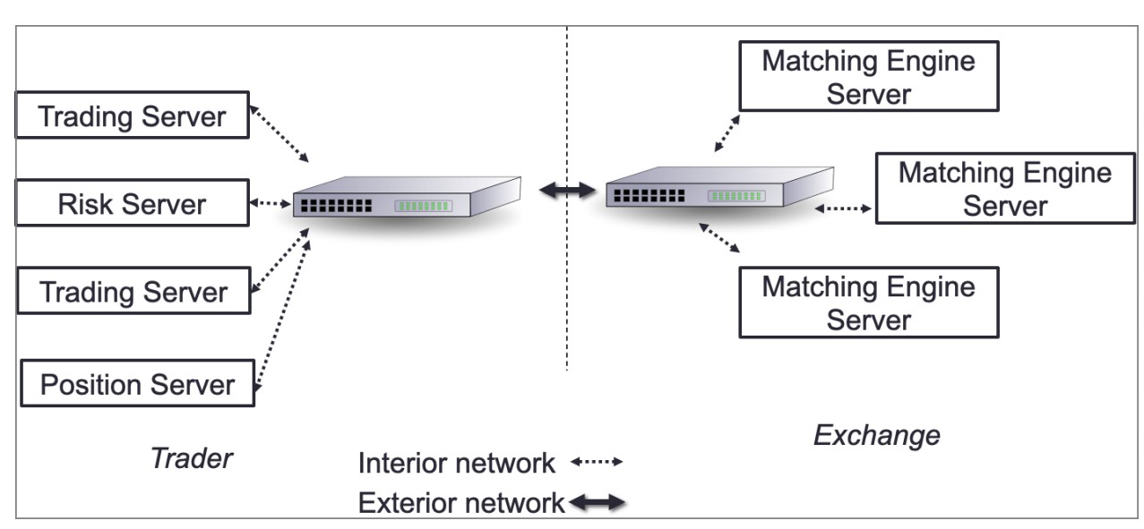
- Interior Network: Connects internal systems within the company.
- Exterior Network: Connects the company’s trading system to external exchanges.
Interior Network
-
Functions:
- Internal market data distribution.
- Signal sharing.
- Order entry.
-
Optimization:
- Minimize hops between hosts to reduce latency.
- Prefer systems that operate purely on the NIC, such as field-programmable gate arrays (FPGAs).
-
Components:
- Switches and Routers: Critical for minimizing network latency.
Exterior Network
- Functions:
- Facilitates communication with external exchanges using native protocols for order entry and market updates.
Understanding the Packet Life Cycle
To optimize communication between the exchange and trading systems, we use copper or optical wire connected to the NIC. These wires transport packets containing market data from the exchange and orders going to the exchange.
Packet Structure
A packet consists of two main parts:
- Headers: Contain information for each layer of the OSI model.
- Payload: Contains the actual data, in this case, a FIX message.
Example FIX Message
8=FIX.4.2|9=95|35=X|34=5|49=NYSE|52=20160617-23:12:05.551|56=TRADSYS|268=1|279=1|269=1|270=110|271=5|37=9|10=209|.
This FIX message will be the payload of the packet.
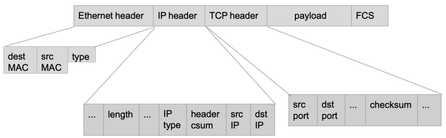
Packet Layers and Headers

- Ethernet Layer: Represents the data link layer.
- IP Header: Represents the network layer.
- TCP Header: Represents the transport layer.
- FCS (Frame Check Sequence): An error-detecting code added to the packet.
Comprehending the Packet Life in the Send/Receive (TX/RX) Path
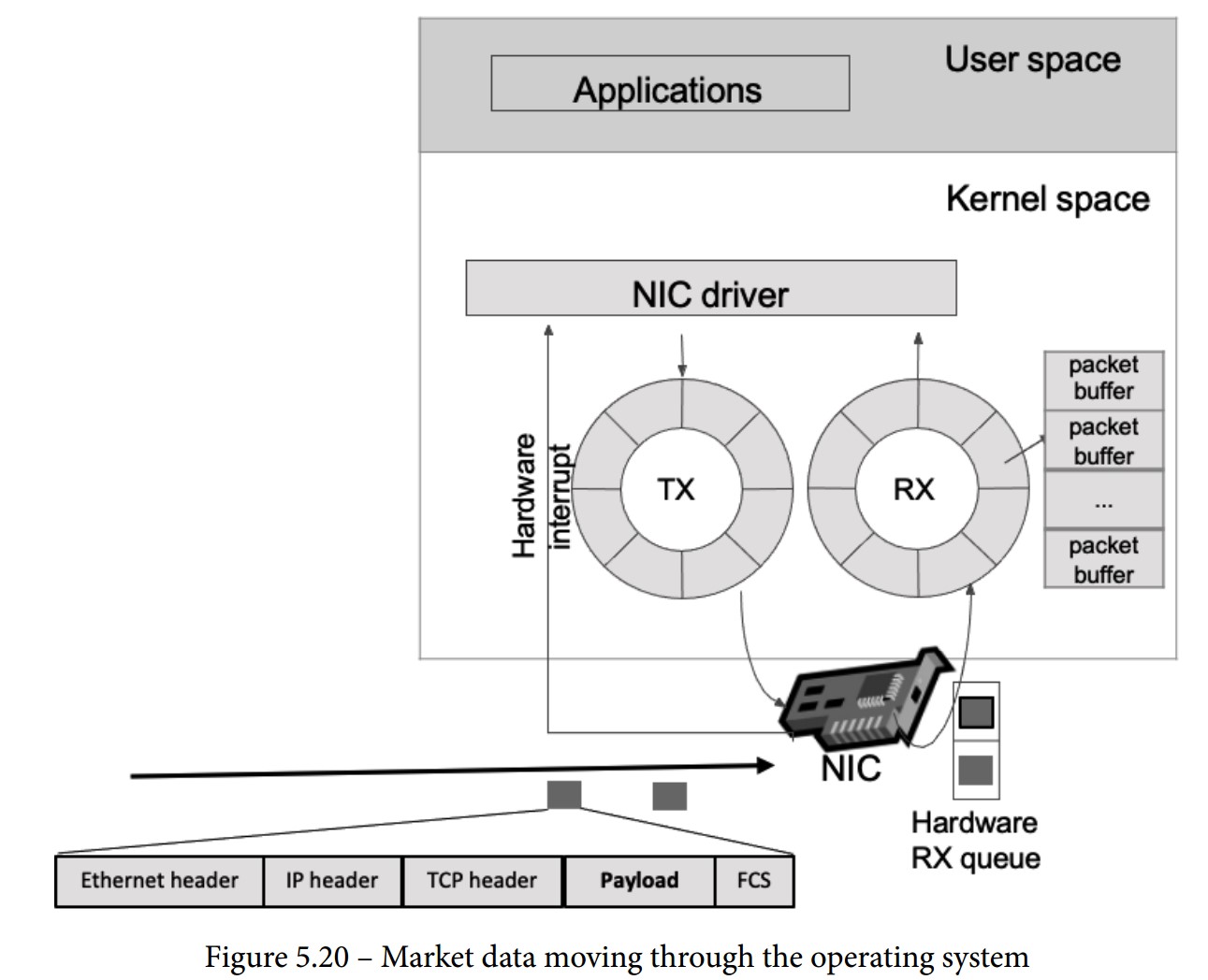
When a packet is sent from an exchange to a trading system, it follows a detailed path through various components and layers. Below are the steps in this path:
-
NIC Receives the Packet:
- The NIC checks if the packet’s MAC address matches its own.
- If it matches, the NIC processes the packet.
-
FCS Validation:
- The NIC validates the Frame Check Sequence (FCS) to ensure the packet is not corrupted (checksum operation).
-
DMA Operation:
- The NIC uses Direct Memory Access (DMA) to copy the packet to the RX buffer.
- RX Buffer: A circular buffer (ring buffer) that helps avoid using locks by having a fixed-size buffer connected end-to-end.
-
Interrupt Handling:
- The NIC triggers an interrupt for the CPU to handle the packet.
- Top Half: Urgent tasks such as acknowledging the interrupt and moving data to a buffer.
- Bottom Half: Further processing is done when the CPU is free (soft interrupt request or soft-IRQ).
- The CPU switches between user space and kernel space, using the Interrupt Descriptor Table (IDT) to call the Interrupt Service Routine (ISR).
-
SK-Buff Allocation:
- The NIC driver allocates a socket buffer (SK-buff or SKB) for each packet.
- SKB: Contains packet headers (metadata) and pointers to the headers and payload.
- The NIC driver updates the SKB with the packet headers, removes the Ethernet header, and passes the SKB to the network stack.
-
Network Layer Processing:
- Verifies the IP address and checksum.
- Removes the network header.
- Compares the IP address against the route lookup.
- Handles packet fragmentation and reassembly if needed.
-
Transport Layer Processing:
- Specific to TCP (or UDP) protocol.
- Manages the TCP state machine.
- Enqueues packet data to the socket read queue.
- Signals that a message can be read in the reading socket.
Software Layer Receiving the Packet
Final Steps in Packet Reception
-
Payload in the Reading Socket:
- The payload, such as a FIX message, is written to the read queue of the socket.
- The operating system schedules the application (trading system) to read data from the socket based on fairness rules.
-
Application Reads Payload:
- The trading system reads the payload from the read queue.
- Begins parsing the FIX message, extracting and interpreting the various tags and values.
Optimization Techniques
-
Network Interface Optimization:
- Use high-performance NICs capable of low-latency operations.
- Employ Direct Memory Access (DMA) to bypass the CPU and speed up memory operations.
-
Efficient Interrupt Handling:
- Minimize interrupt handling time by efficiently managing top half and bottom half processing.
- Use advanced NIC features like interrupt coalescing to reduce interrupt overhead.
-
Buffer Management:
- Optimize buffer sizes and use circular buffers to avoid locking mechanisms.
-
Protocol Efficiency:
- Utilize efficient protocols like FAST for market data to reduce parsing time.
- Implement binary protocols such as ITCH/OUCH for faster data processing.
-
Hardware Acceleration:
- Use FPGAs or other hardware accelerators to handle specific tasks like parsing and processing packets.
-
Software Optimization:
- Write performance-critical code in low-level languages like C/C++.
- Optimize system calls and reduce context switches.
Monitoring the Network in HFT
Key Aspects of Network Monitoring
-
Packet Capture and Analysis:
- Definition: Capturing Ethernet frames for examination or analysis.
- File Format: Packet capture files are typically saved in the .pcap format.
- Usage: Commonly used for network troubleshooting and security analysis.
-
How Packet Capture Works:
- Methods:
- System-Level Capture: Capturing packets directly from your system.
- Network Equipment: Using routers, switches, or dedicated hardware like a Test Access Point (TAP) for packet capture.
- Modes:
- Promiscuous Mode: Network interfaces capture all packets, not just those destined for them.
- Monitor Mode: Useful for capturing packets in a wireless network.
- Methods:
-
Limitations of Packet Capture:
- Local Capture: Only captures activity on the local switch port.
- Promiscuous Mode: Provides a broader view but still limited to the local network segment.
-
Advanced Packet Capture Techniques:
- Port Mirroring: Duplicates network traffic and sends it to a specific port.
- Port Monitoring/SPAN: Similar to port mirroring, used on routers and switches to capture traffic for analysis.
-
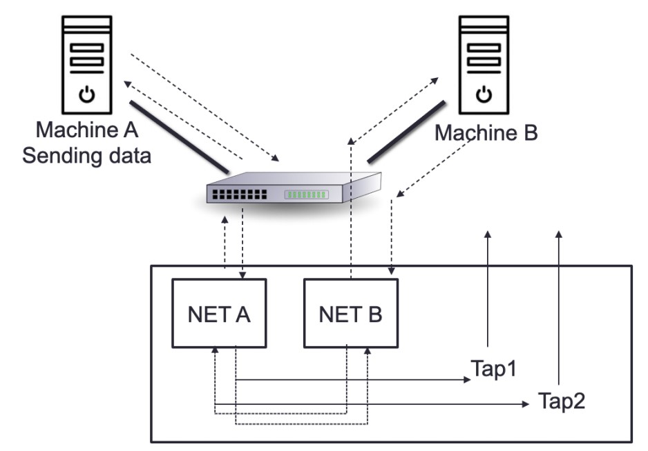
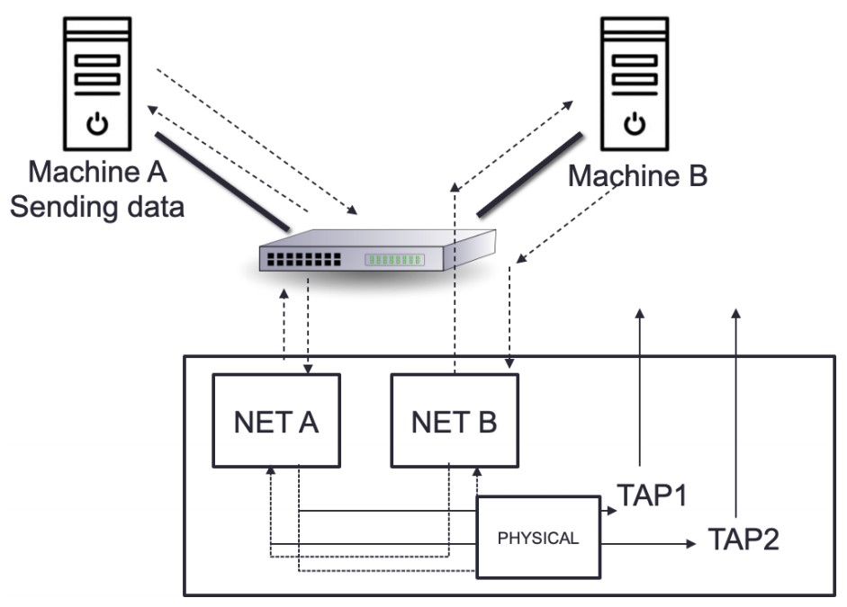
Using Dedicated Network TAPs (Test Access Points):
- Purpose: Ideal for capturing packets on large or busy networks.
- Advantages: No performance impact since they are dedicated hardware.
- Setup: Captures both directions (transmit (TX) and receive (RX)) to provide a complete picture of network traffic.
Packet Capture Tools
-
Wireshark:
- A popular tool for capturing and analyzing network traffic.
- Provides detailed insights into packet contents and network performance.
-
tcpdump:
- A command-line packet analyzer.
- Useful for capturing packets and troubleshooting network issues.
-
Hardware-Based Capture:
- TAP devices and switches with built-in packet capture capabilities.
- Often controlled via command-line interface (CLI) or user interface (UI).
Monitoring Metrics
-
Data Loss:
- Track packet loss to identify network issues that could affect trading performance.
-
Latency:
- Measure round-trip time (RTT) and other latency metrics to ensure quick order execution.
-
Interruption:
- Monitor network stability and identify interruptions that could disrupt trading operations.
Ethernet TAPs: Passive vs. Active
TAPs (Test Access Points) are critical for network monitoring, allowing for the capture and analysis of network traffic. They come in two main types: passive and active, each with distinct features and trade-offs.
Passive Network TAP
-
Definition:
- A passive TAP has no physical separation between its network ports, meaning it can continuously monitor traffic without affecting the network flow. Traffic continues to flow even if the device loses power.
-
Functionality:
- Power Independence: Fiber TAPs do not require power to operate and maintain connection during power loss. Copper TAPs, though requiring power, still function as passive devices because they have a direct connection between ports.
- Usage: Commonly used for monitoring 10/100M copper interfaces and fiber connections.
-
Copper TAPs:
- Power Requirement: Need electricity to function but retain their passive nature due to their direct connectivity.
- Operational Reliability: The link remains operational even during power loss.
-
Fiber TAPs:
- No Power Requirement: Operate by splitting incoming light into two or more paths, independent of external power sources.
- Resilience: Maintains connectivity during power failures.
-
Advantages:
- Reliability: Immediate failover with no delay due to power loss.
- Power Efficiency: Fiber TAPs do not need electricity.
-
Disadvantages:
- Power Dependency: Copper TAPs require power, although they are still considered passive.
Active Network TAP
-
Definition:
- An active TAP features physical separation between network ports due to its electrical components and requires power to operate.
-
Functionality:
- Power Dependency: Needs a fail-safe mechanism to maintain traffic flow during power outages. Uses relays to ensure that traffic continues even when power is lost.
- Operation: Relays keep open while powered and switch to direct traffic flow through the TAP during a power outage.
-
Advantages:
- Traffic Continuity: Ensures reliable traffic flow with a fail-safe mechanism that can handle power disruptions.
- Versatility: Suitable for complex network environments where active traffic management is required.
-
Disadvantages:
- Power Requirement: Requires electricity to operate and manage relays.
- Complexity: The relay system adds complexity and potential minor delays during failover.
Trade-offs Between Passive and Active TAPs
-
Passive TAPs:
- Advantages:
- No power requirement for fiber TAPs, ensuring reliability.
- Immediate failover with no delay.
- Disadvantages:
- Copper TAPs, while still passive, require electricity.
- Advantages:
-
Active TAPs:
- Advantages:
- Provides a reliable fail-safe mechanism to maintain traffic flow.
- Ensures continuous traffic management even with electrical components.
- Disadvantages:
- Requires power and includes a more complex relay system.
- May introduce a minor delay in failover.
- Advantages:
Valuing Time Distribution in HFT
Importance of Time in HFT
In HFT, time is the most critical resource. Accurate timing ensures the correct execution of trading models and strategies, as order execution often depends on the precise arrival time. Therefore, synchronization of time between trading systems and exchanges is essential.
Time-Synchronization Services
Global Positioning System (GPS) and Global Navigation Satellite System (GNSS)
- Purpose: Provide precise time using atomic clocks.
- Usage: Ensures worldwide availability of precise time without additional engineering.
Network Time Protocol (NTP)
- Function: Synchronizes computer uptime with a time server.
- Layers (Strata):
- Stratum 0: Highest layer, uses GNSS satellites.
- Stratum 1: Directly connected to Stratum 0 clocks, achieving microsecond-level synchronization.
- Stratum 2: Connects to multiple Stratum 1 servers.
- Stratum 3-15: Additional layers provide varying accuracy.
- Accuracy: Can deliver timestamps accurate to the order of picoseconds. Future developments may introduce 128-bit timestamps for femtosecond accuracy.
Precision Time Protocol (PTP)
- Function: A network-based time synchronization standard designed for high precision.
- Accuracy: Strives for nanosecond or picosecond precision.
- Hardware Timestamping: Uses hardware instead of software for timestamping, providing higher resolution.
- Pulse-Per-Second (PPS) Signals: Achieves accuracy from 12 picoseconds to a few microseconds per second.
Importance of Timing in HFT
-
Timestamp Accuracy:
- HFTs require accurate Coordinated Universal Time (UTC) for order timestamps to track market orders precisely.
-
LAN Synchronization:
- HFT systems often run multiple computers on dedicated LANs, using a single PTP grandmaster clock per LAN.
- Each computer on the LAN syncs to this grandmaster, which in turn, takes time from an external source.
- A grandmaster is necessary for each physical location to ensure accurate time synchronization.
-
Performance Analysis:
- Accurate timestamps are crucial for analyzing log files and trading activity.
- Understanding LAN latency is vital for optimizing HFT performance.
-
Latency Reduction:
- Co-located HFTs reduce latency to below 5 microseconds, compared to 1-5 milliseconds for non-co-located traders.
- This significant reduction allows co-located HFTs to process market data faster.